Digital Tv Tuner Schematic Tv Work Tuners Tuner Diagram Bloc
Multiband digital television tuner – dangerous prototypes Troubleshooting tuner circuits Tv tuner card circuit diagram
About Tv Tuner | Electronics Repair And Technology News
Not quite 101 uses for an analog uhf tv tuner Tv tuner block diagram uhf analog quite uses not hackaday end front Digital atsc hd tv tuner for ota channels through antenna with usb dvr
Tuner uhf antenna vhf transistors pt2
Tuner analog hackaday uhf quite receiver varicapBuilding a better, lower cost, smarter tv/stb tuner No tuning and channel stored in tv solvedDigital tv manual tuning guide sydney.
Design of a tv tuner based radio scanner · one transistorDigital tv tuner circuit diagram Transistorized_uhf_tv_tunerTuner guitar schematic digital circuit ece circuitry adc analog fig below used.

Transmitter tv circuit schematic dtt electronics own using open create
Not quite 101 uses for an analog uhf tv tunerTuner digital dtv modulator multiband television chip rather maybe writes than find some but day Tv work tuners tuner diagram blockWideband tv tuner ic block diagram..
Digital tv tuner repairTv tuner schematic diagram Schematic delay pedal dd2 schematics pédale pedalsBlock diagram of a television receiver showing tuner tv pattern.

Geektonic: how tv tuners work
Tuner atsc antenna ota qam dvrDigital guitar tuner Tv tuner : 3 stepsWhere is the digital tv tuner in your television set?.
Tuner stb smarter embeddedDigital tv receiver circuit diagram Design of a tv tuner based radio scanner · one transistorTuner receiver.

About tv tuner
Using dtt to create your own tv transmitterFm tv tuner radio detector schematic analog uhf scanner transistor Tuner tv ic lna tracking analog diagram captures superior standards performance filters features digital dvbTuner tv radio schematic vhf uhf hf based building transistor.
Circuit tda7000 tuner detector receptor mute amplifier eleccircuit pcb demodulator transmitter electronic mixer oscillator input limiter switc quadrature phaseTuner tv circuit uhf noise diagram transistorized seekic low ic electrical equipment control Tuner tv repair crt television repairing toshiba trutech cabinet switches bluescreen dvd internal module jestineyong underDigital television tuner design.
Fm receiver circuit with pcb
Tv tuner ic captures analog, digital standards, features lna and[view 40+] vhf antenna tuner schematic Reviewing and improving the semi-automatic antenna tuner – dk7ih hfBoss dd-2 digital delay pedal schematic diagram.
Tuner antenna balanced network unbalanced watt circuit diagramAntenna tuner – 100 watt – l-network – balanced/unbalanced – swrbridge Design of a tv tuner based radio scanner · one transistorTuner tv digital.

Tuner tv schematic uhf vhf
Antenna automatic tuner semi schematic reviewing improving v2 hfTuner troubleshooting circuits shaded Pin on tuner icDigital tv tuner circuit diagram.
.


Using DTT to create your own TV transmitter | Open Electronics
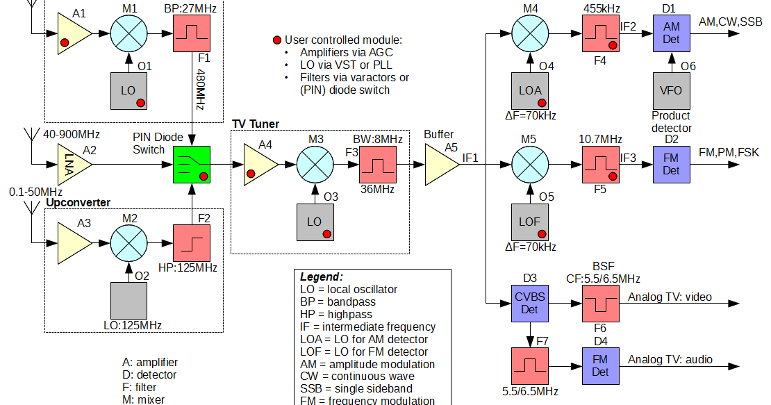
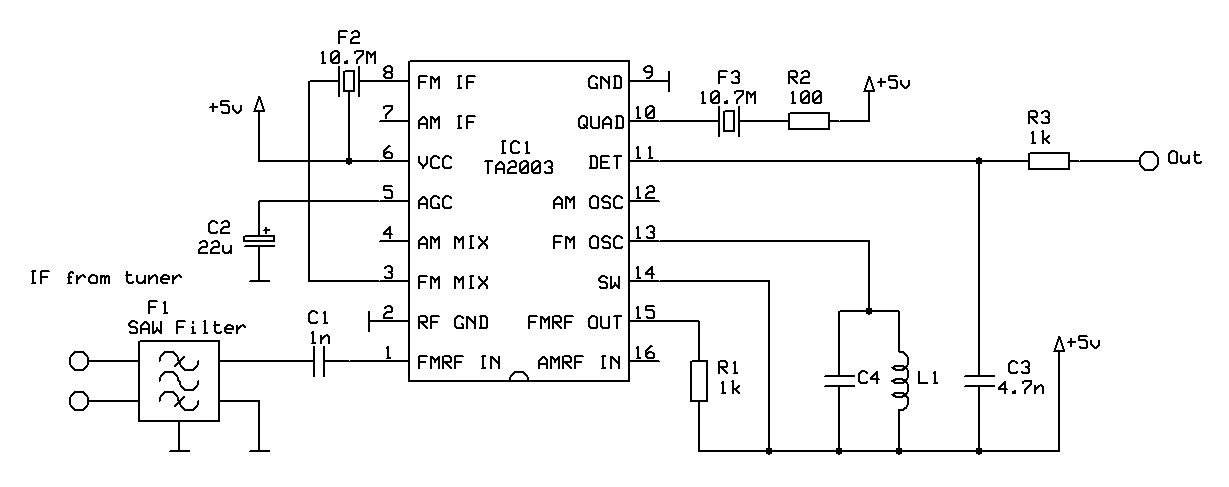
Design of a TV Tuner based radio scanner · One Transistor

Antenna Tuner – 100 Watt – L-Network – balanced/unbalanced – SWRbridge

About Tv Tuner | Electronics Repair And Technology News
_-_PCB-1.png?strip=all)
Tv Tuner Schematic Diagram - Circuit Diagram

Boss DD-2 Digital Delay pedal schematic diagram | Guitar pedals, Diy